I have been asked several times how I build the chassis for my freight cars, and particularly how I attach the trucks and couplers. I have added this page because building a chassis was something that I avoided for quite some time, believing it to be too difficult to get a good running model. However once I worked out a method and started building I found out that it is not much harder, and in some cases can be even easier, than trying to convert an N gauge chassis to do the job.
Rather than just describe how I build a chassis, I have decided to show the steps as I build a flat car. The car I am building will use Bachmann N scale trucks and DG couplers.
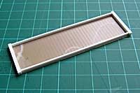
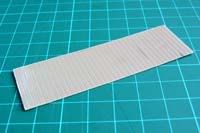 The first stage is to cut out the car floor.
For this I used Slaters 2mm scribed plasticard, which scales out to represent 8" planking.
My model will represent a 23' x 7' car so I cut the floor to be 80mm x 25mm.
The dimensions can of course be varied to suit whichever car you are building, but do take care to get this measurement right as everything else will be based from it.
Having said that, although I ensured that the width was as measured, I cut the length to align with the nearest whole plank on the decking.
This could affect the car length by +/- 1mm, but as it is a freelance car anyway I do not suspect anyone will notice!
The first stage is to cut out the car floor.
For this I used Slaters 2mm scribed plasticard, which scales out to represent 8" planking.
My model will represent a 23' x 7' car so I cut the floor to be 80mm x 25mm.
The dimensions can of course be varied to suit whichever car you are building, but do take care to get this measurement right as everything else will be based from it.
Having said that, although I ensured that the width was as measured, I cut the length to align with the nearest whole plank on the decking.
This could affect the car length by +/- 1mm, but as it is a freelance car anyway I do not suspect anyone will notice!
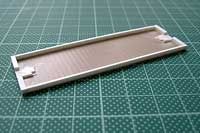
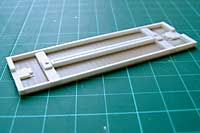
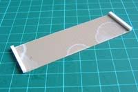 Next I cut out and attached the two end sills.
On the type of car that I am modeling these would have been cut from timbers of around 8" x 8", so I cut them from 80th square Evergreen styrene strip.
These should be cut such that the length matches the floor width.
I find the easiest method of cutting them so that they are square and to the correct length is to first cut them slightly over length and then sand the ends back carefully on wet and dry paper until they fit.
Next I cut out and attached the two end sills.
On the type of car that I am modeling these would have been cut from timbers of around 8" x 8", so I cut them from 80th square Evergreen styrene strip.
These should be cut such that the length matches the floor width.
I find the easiest method of cutting them so that they are square and to the correct length is to first cut them slightly over length and then sand the ends back carefully on wet and dry paper until they fit.
Note from the diagram how I attach the end sill so only half its width is attached to the decking - this represents a prototype where the decking was not laid to the very end of the frame.
 I then cut two side sills from 40th x 80th Evergreen strip, to represent prototype timbers that were close to 4" x 8".
Again I initially cut these slightly over length and then carefully sanded them back for a perfect fit.
Check the car you are modeling for positioning of these parts - on the car I am building the deck planks are wider than the side sill, so I added them about 0.5mm in from the edge of the deck and the end sills.
Once these are attached things will start to take on some strength, and also begin to look more like a chassis.
I then cut two side sills from 40th x 80th Evergreen strip, to represent prototype timbers that were close to 4" x 8".
Again I initially cut these slightly over length and then carefully sanded them back for a perfect fit.
Check the car you are modeling for positioning of these parts - on the car I am building the deck planks are wider than the side sill, so I added them about 0.5mm in from the edge of the deck and the end sills.
Once these are attached things will start to take on some strength, and also begin to look more like a chassis.
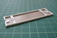
 The next step is to create a mounting pad for the coupler.
The pad I use has a shape and a height specifically for DG couplers (with the corners trimmed for wheel clearance), if you do not use DGs then you may need to vary this pad to suit your chosen couplers.
Due to the height at which I set the car floor above track level (determined by the height of the bolsters) this pad needs to be 40th deep on my cars.
Although I could easily have used use a single piece of 40th plasticard, I did not have any to hand at the time, so I used a piece of 10th cut to a rectangle plus a piece of 30th cut to the shape of the coupler.
The next step is to create a mounting pad for the coupler.
The pad I use has a shape and a height specifically for DG couplers (with the corners trimmed for wheel clearance), if you do not use DGs then you may need to vary this pad to suit your chosen couplers.
Due to the height at which I set the car floor above track level (determined by the height of the bolsters) this pad needs to be 40th deep on my cars.
Although I could easily have used use a single piece of 40th plasticard, I did not have any to hand at the time, so I used a piece of 10th cut to a rectangle plus a piece of 30th cut to the shape of the coupler.
 Having attached the coupler mounting pad behind the end sills the next step is to notch the sills such that the centre section is the same height as the pad.
Why not have the couplers mounted to the bottom of the sill (as per the prototype)? Simply because I feel that doing this, with a standard height DG coupler, results in a car that rides to high.
I could have chosen to mount my couplers lower, but I specifically wanted to retain compatabilty with my existing 009 stock so decided to go with notched end sills.
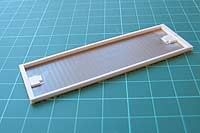
 The next stage is to build and attach the bolsters.
I cut the main bolster from 60th strip. This is cut full width to fit between the side sills.
I then add a mounting pad to the centre of the bolster from 30th plasticard.
This should be wide enough to support the chassis on the truck, but narrow enough to clear the wheels to allow for truck swing.
I will also round the corners on this pad so that will not catch on the truck during operation.
At this point the assembly should be left at least overnight to ensure the joint is thoroughly hardened before drilling.
Mark the centre point on the bolster and drill through with a 1.4mm bit.
Once done carefully tap the hole using a 10BA tap.
After ensuring the tapped hole is clean the bolster can be attached to the chassis.
My usually method to determine the positioning of the bolster to get the correct look for the cars I am modeling is to set it back from the car end by a distance equal to the wheelbase of the trucks I will be using.
Test fit at this position before glueing - the bolster may need to be moved depending on your truck/coupler combination.
The next stage is to build and attach the bolsters.
I cut the main bolster from 60th strip. This is cut full width to fit between the side sills.
I then add a mounting pad to the centre of the bolster from 30th plasticard.
This should be wide enough to support the chassis on the truck, but narrow enough to clear the wheels to allow for truck swing.
I will also round the corners on this pad so that will not catch on the truck during operation.
At this point the assembly should be left at least overnight to ensure the joint is thoroughly hardened before drilling.
Mark the centre point on the bolster and drill through with a 1.4mm bit.
Once done carefully tap the hole using a 10BA tap.
After ensuring the tapped hole is clean the bolster can be attached to the chassis.
My usually method to determine the positioning of the bolster to get the correct look for the cars I am modeling is to set it back from the car end by a distance equal to the wheelbase of the trucks I will be using.
Test fit at this position before glueing - the bolster may need to be moved depending on your truck/coupler combination.
 The centre sills can now be added.
Once these are in place the chassis will become much more rigid.
Many prototype cars had four centre sills, adding these makes the chassis even more rigid but they do then get in the way of the wheels when the truck swings.
For that reason I usually skip prototype practice and only add the centre two sills, which I keep close to the centre of the car to give good clearance between the wheels.
I use the same 40thx80th strip for these sills as I used for the side sills
The centre sills can now be added.
Once these are in place the chassis will become much more rigid.
Many prototype cars had four centre sills, adding these makes the chassis even more rigid but they do then get in the way of the wheels when the truck swings.
For that reason I usually skip prototype practice and only add the centre two sills, which I keep close to the centre of the car to give good clearance between the wheels.
I use the same 40thx80th strip for these sills as I used for the side sills
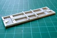 The final pieces of 'structural timber' to add are the needle beams.
On the prototype cars these beams are a critical structural item, holding the side and centre sills in alignment and provide a mounting point for the queen posts.
The size of these beams varies from car to car.
On a previous car I used 40th square strip to represent 4" square timbers, but on this car I have used 40th x 80th to represet 4" x 8".
It is down to personal opinion, and the car you are modelling, as to which will appear best.
The final pieces of 'structural timber' to add are the needle beams.
On the prototype cars these beams are a critical structural item, holding the side and centre sills in alignment and provide a mounting point for the queen posts.
The size of these beams varies from car to car.
On a previous car I used 40th square strip to represent 4" square timbers, but on this car I have used 40th x 80th to represet 4" x 8".
It is down to personal opinion, and the car you are modelling, as to which will appear best.
The 'chassis' part of the model is now complete except for attaching the trucks and couplers, but as this is a flatcar I will first mention the final detailing steps.
I will add photographs to the section when I progress the car I am building to this level.
Stake Pockets. Not all flatcars had these, although most did, so I will be adding them. These scale out quite small and although accurate detail items are available I feel they often look oversize. That being the case I model these with a simple cube chopped from 40th square plastic strip. Whilst this may sound as though it would look like a crude attempt to model an open stake pocket, the realitity is that given their small size they do an acceptable job.
Queen Posts. Most wooden chassis cars would have had these, although not all. Some cars were built, or modified later, to just use wooden blocks. If modeling wooden blocks then I would just use short lengths chopped from plastic strip, otherwise I use Grandt Line items. To attach the queen posts I cut off the mounting pin and just glue them to the needle beam, rather than drilling a hole for the pin.
Turnbuckles and Truss rods. Turnbuckles were another item that were usually seen on a car, although not always. When modeling them I again use Grandt Line items. I thread these onto fishing line (I think I used 5lb line, but not certain of this). I would use a small amount of CA, or superglue, to attach each turnbuckle to a length of line and then glue the line across trhe top of a set of queen posts. Attaching the other end of the line to the car is the tricky bit! If you use the prototype alignment then it will foul the wheels when the truck swings - this was not a problem on the real car due to the far less severe curves they were designed to operate on. For this reason I usually set the rods to a steeper angle such that they will clear the wheels. I would attach these using scraps of plastic strip glue to the chassis such that the line can pass beneath them and, when these have fully dried, glue the line under them with CA while holding it tight.
Brake wheel.
This would be the final detail that I would add.
I would actually not add it until after the truck and couplers were fitted, because once it is in place you can no longer easily turn the car upside down to work on it.
I am currently looking for a UK based supplier of suitable brass brake wheel etchings, but if I do not find one then I know that they can be ordered from the US.
For the brake staff I would use a length of springy wire of a dimension to fit the hole in the brake wheel, the steel wire supplied in the DG couplers kit seems just about right.
The last step before fitting the trucks and couplers would be to paint the car.
For the type of car I am modeling that means painting the decking to represent unpainted wood, and then painting everything else visible in a brown/boxcar red colour.
And on to the last step - fitting the trucks and couplers. In reality I would have probably have test fitted the trucks well before now, although I would not permanently attach them until this point.
And finally, in the best Blue Peter tradition...here is one I prepared earlier!
NB: This car has Grandt Line trucks fitted
also, it is still missing truss rods/turnbuckles and a brake wheel.